CAD-as-code.
This site keeps saying the loop is general: describe, generate, verify, commit. This edition is the strongest evidence I can offer, because the artifact isn't a web page. It's a wall frame — a physical, printable object designed the way this book says everything should be designed: as code, in a session, with the verification built in.
One session. Input: the vendor's dimensional drawing, a PNG. Output: eight printable parts as STL and STEP, an assembly model with the panel and Pi mocked in place, section cuts, and the isometric line renders on this page — projected from the same geometry. The parts' single source of truth is a 267-line Python script. I never opened a CAD program.
Jump to section tap to open
The claim
Every chapter of this book runs the same loop on information: describe the thing, let the model generate it, verify against something that can't be sweet-talked, commit. The quiet assumption was that the loop ends where the screen does. It doesn't.
The frame on this page was designed by Claude Code in one session. Not "AI-assisted" in the sense of autocomplete inside Fusion 360 — there was no Fusion 360. The design is a Python script. The STL files your slicer eats and the STEP files a machinist could edit are build artifacts, regenerated from source in seconds. When a dimension turns out wrong, you don't re-sculpt a mesh; you change a number at the top of the file and rerun.
If you read Music is Math, you already know the shape of this argument: a domain falls to the loop the moment someone finds its alphabet. Geometry's alphabet turned out to be embarrassingly small — boxes, cylinders, boolean subtraction, a fillet. A language model is bad at holding a mouse and excellent at writing programs, so the move was never "teach the model CAD." It was: pick the representation where the model is already strong.
The wall it hangs on
Context, because the frame is the last mile of a longer build. There is a bird station at my window: a Raspberry Pi with a microphone, listening around the clock, classifying every call with BirdNET and keeping a live collage of the last 24 hours of visitors. On the wall, a 13.3-inch six-colour e-ink panel — a Pimoroni Inky Impression, $299.99 — mirrors that collage, repainting only when the birds change. E-ink holds its image unpowered; the birds stay on the wall even if everything else dies. That failure mode is a feature.
The gentle version of the recipe mats the panel into a $22 wood photo frame, and for a Pi Zero tucked behind it, that works. The live install is not the gentle version. It runs a full Raspberry Pi 5 mounted on the panel's own booster header — thicker, hotter, with four side buttons that need to stay reachable, a USB-C power lead, and the microphone's cable arriving from the window. No off-the-shelf frame holds that stack, hides the cables, breathes enough to cool it, and still reads as a picture instead of a gadget.
So the ask was an interior-design brief, not an engineering one: make the electronics disappear. It should hang flush like a matted print, in landscape or portrait, and nothing about it should say "computer." The engineering below is what the model did with that brief.
The spec was a PNG
A frame lives or dies by fit, and fit needs numbers. The numbers came from Pimoroni's official dimensional drawing — an image, read by the model the way you would read it, then written down as constants. Board 296.7 × 210.0 mm. Glass 284.7 × 208.8. Active display area 270.4 × 202.8. The four side buttons at ±25.35 and ±76.05 mm from centre. The Pi mounting holes, 58 × 49, positioned 107.6 mm from the right board edge and 100.1 from the bottom.
That drawing is committed next to the generator in the repo, which makes the trust chain auditable: every constant in the script cites a place on the drawing you can check with your own eyes. This matters more in hardware than in prose. A hallucinated sentence costs a correction; a hallucinated millimetre costs a print.
It is also the part of the process that generalizes furthest. Every bracket, mount, and enclosure you've ever almost designed has a vendor PDF with a dimensional drawing on page 2. That drawing has always been machine-readable in principle. Now it is machine-readable in practice.
The CAD is a program
The generator uses build123d, an open-source Python CAD library. The whole frame — front, back, every hole and joint — is 267 lines. The top of the file is a parameter block that reads like a config, because it is one:
PANEL_T  = 4.5   # panel edge thickness — verify with calipers; foam absorbs ±1.5
REVEAL   = 0.8   # opening margin outside active area, per side
INTERIOR = 34.0  # depth behind panel: booster + Pi 5 + ports ~30
FACE_W_TB = 19.0 # face border width, top/bottom
And the geometry itself is boolean algebra. The front frame, in four lines: start from a solid block, subtract the opening, subtract the pocket the panel drops into, subtract the recess the back cover sits in.
ring  = box(OUTER_W, OUTER_H, DEPTH)
ring -= box(OPEN_W, OPEN_H, DEPTH + 2, z=-1)      # opening (through)
ring -= box(POCK_W, POCK_H, DEPTH, z=FACE_T)      # panel pocket + cavity
ring -= box(RAB_W, RAB_H, RABBET_D + 1, z=RAB_Z)  # back cover rabbet
Run it and the script writes out every part as both STL and STEP. The distinction matters. STL is a dead pile of triangles — fine for a slicer, useless for a human who wants to change anything. STEP is the living solid: open it in Fusion or FreeCAD and the faces are still faces. Shipping both is the hardware version of send the link, not the file — one format to consume, one to keep working on.
And because STEP is a text format, the whole design went into git like any other source: one commit, 25 files, 77,177 insertions, of which the assembly model alone is 23,375 lines. Version control now covers an object. When the frame gets a Mk II, the diff will show exactly which walls moved.
Six decisions in plastic
"The model wrote a script" undersells what happened, because the script encodes mechanical judgment. These six decisions are where the design earns the word, and every one of them is a constraint I would not have thought to state up front.
- 1 — Clamp, don't screw. Nothing fastens into the display. The panel drops into a pocket behind the front lip, and the back cover carries six ø8 mm posts that press it against the lip through 3 mm EVA foam pads. The foam is the point: the panel's edge stack is set at 4.5 mm in the script, and the foam absorbs ±1.5 mm of reality. The tolerance lives in the material, not in your measuring skills. The Pi never touches the frame at all — it stays on Pimoroni's own booster header and standoffs.
- 2 — The 0.8 mm reveal. The opening is drawn 0.8 mm outside the active display area on every side, so the panel's own black border vanishes behind the lip. The image reads edge-to-edge, like a matted print. That is the entire "museum" effect, and it costs less than a millimetre.
- 3 — Split for the bed you own. The front frame is 312 mm wide — bigger than most print beds. So the script also emits it as four quadrants joined by half-lap joints, each quadrant at most 172 × 138 mm, which fits a 220 × 220 bed. The back cover splits into two dovetailed halves. Joint clearance is 0.15 mm, and the cover screws double as the clamp while the glue cures. The split is not a concession bolted on afterwards — it is parametric, generated from the same source as the one-piece version.
- 4 — The finish is the plate. Front quadrants print face-down on a textured build plate, so the plate's texture becomes the frame's visible finish — no sanding, no supports anywhere on any part. Vents and the cable tunnel print as bridges; the side screw bosses carry built-in 45° cones so they self-support. Printability wasn't checked after the design; it was designed in.
- 5 — Design for living with it. The four side buttons get a dedicated channel with 4 mm of clearance, so the frame never presses them and they stay reachable with the cover off — maintenance costs nine screws, not a disassembly. Power and mic leads lay into an open tunnel through the bottom wall — no threading connectors through holes — and the cover's notch closes over them; three zip-tie saddles inside the cover keep the slack off the panel's back. Chimney vents top and bottom pull air past the Pi. Four keyholes, recessed so the frame sits flush: one pair for landscape, one for portrait.
- 6 — The microphone never comes inside. The obvious tidy-up — tuck the mic into the frame — would muffle the station's hearing and quietly degrade the whole system upstream. Only the cable enters; the capsule stays on its window mount. The best design decision in the file is a refusal.
The bill of materials for all of it: nine M3×10 screws that self-tap into printed pilots (no inserts), six squares of foam tape, two wall screws, three small zip ties, and glue for the laps. About 720 grams of filament.
The script QAs its own geometry
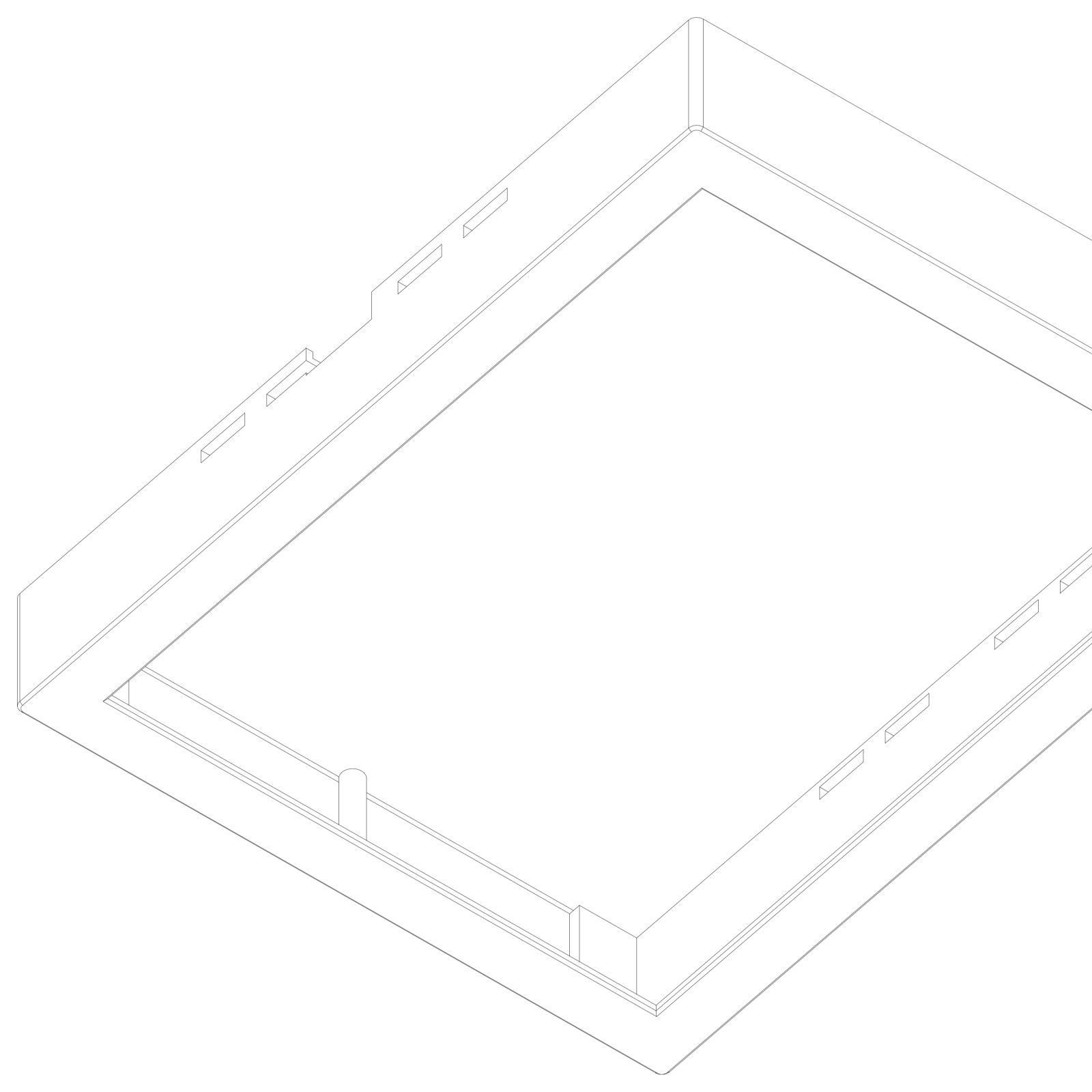
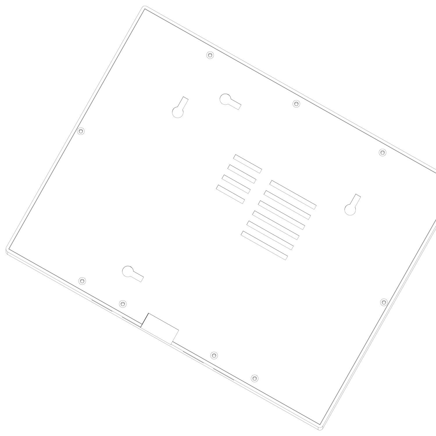
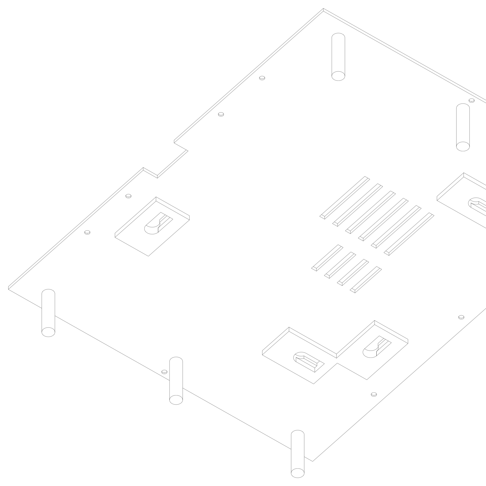
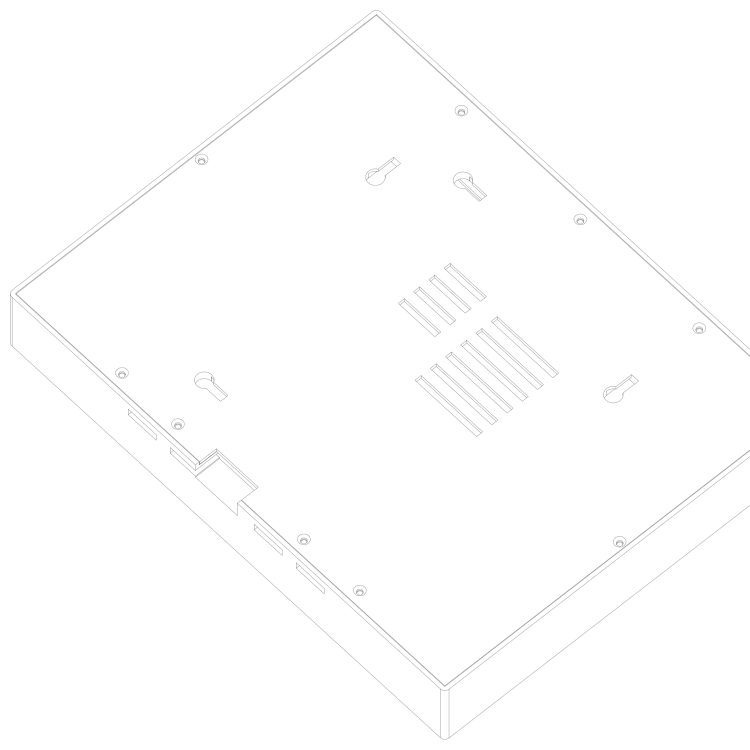
Here is the part that makes this an operator lesson and not a maker anecdote. The final 60 lines of the script are not design — they are verification. Every run prints a report for every part: volume, bounding box, and whether the solid is geometrically valid. Then it cuts the parts open at five heights and exports the cross-sections as SVGs — the CAD equivalent of a unit test, because a wall that's too thin or a pocket that broke through shows up as a wrong outline you can see in two seconds. Then it projects the solids to isometric line drawings for eyeball QA — the line renders below come from that projection stage, run from several viewpoints during the session, and are committed beside the parts. Finally it exports a full assembly STEP with a mock panel and a mock Pi positioned inside, so a human can open one file and sanity-check that everything claimed to fit actually fits.
The model cannot hold calipers, so it does the next best thing: it manufactures evidence a human can check fast. That is the same division of labour every chapter here argues for — the generator is never the judge. The renders you're looking at are that evidence, unretouched.
Where this honestly stops
The rule of this site is that the failure modes ship with the story. Four apply.
1 — Nothing is printed yet. The commit message says it in plain text: the panel-thickness and interior-depth parameters await calipers before printing. The design is committed; zero grams of plastic exist. A ±1.5 mm foam window is a hypothesis until it has compressed against a real panel, and this page will not pretend otherwise. When the print happens, the receipts — including anything that didn't fit — belong here.
2 — The dimensions are read, not measured. Every number traces to the vendor's drawing, which is the right provenance — but a vision model reading a PNG is a trust chain, not a caliper. The mitigation is structural: because the design is parametric, a mis-read number is a sixty-second regeneration, not a redesign. This is the real argument for CAD-as-code, stated as risk management.
3 — Iteration costs mass here. In software the loop is free to run; here one turn of the loop is ~720 grams of filament and its hours on the printer. Same loop, priced differently — which is why the self-verification stage is load-bearing rather than decorative. You spend cheap render-checks to avoid expensive plastic-checks. If your instinct is that this makes agents worse suited to hardware, invert it: the more a mistake costs, the more the front-loaded, machine-generated evidence is worth.
4 — Mouse CAD is not the villain. The same repo's earlier hardware — the bird-mic enclosure and its window mount — was drawn by hand in Fusion 360, by a collaborator, and it works fine on the window today. The difference is what each artifact invites. An .f3d file needs its author and a licence; a parameter block with comments invites anyone — including the next model, in the next session — to change one number and rerun. Source beats binary for the same reason it always has.
Do this Monday
You have a bracket. Everyone has a bracket — the mount, the spacer, the enclosure, the jig you've been meaning to make for a year. That's the Monday move.
Find the vendor drawing first. The dimensional drawing in the datasheet PDF is the whole game. Attach it to the session and ask the model to read the dimensions back to you before any code — you're checking the trust chain at its weakest link, once, out loud.
Then ask for a program, not a model. Name the stack — build123d or CadQuery if you want Python, OpenSCAD if you want the older, simpler thing — and demand five artifacts: a commented parameter block at the top; STL and STEP for every part; an assembly file with mock-ups of the bought components sitting in place; section cuts at the heights where the fit is tightest; and a printed validity report per part. If your printer's bed is small, say its size — a parametric split like the quadrants above is a one-sentence request.
Then caliper the one number the design leans on. Every enclosure has one dimension that everything else forgives — here it's the panel's edge thickness, and the design says so in a comment. Measure that one for real before you print. It is the single minute of physical effort the whole loop asks of you.
Related: Ch 45 — the App Store without Swift, the same bet in a different domain · Ch 23 — a Saturday build, hour by hour · Music is Math — why domains fall when the alphabet is found · Ch 41 — send the link, not the file · Glossary
Every number on this page comes from the committed sources in the belkins-birdnet repo — the generator script, the repo's READMEs (including the frame BOM), and the commit of 2026-08-03 — and was re-verified against them on 2026-08-03, by a four-lane adversarial pass that checked 189 claims and corrected 8. The design is committed; the print is pending calipers, and this page says so rather than papering over it. Corrections: v@vladyslavpodoliako.com